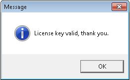
Once the key has been validated, a message will indicate success.
1. Installation and Licensing
http://iosix.com/IOSiX-3.6.7.exe
It is highly recommended that the user account used for installation be the intended user account for software operation. Attempting to do otherwise may cause some complications.
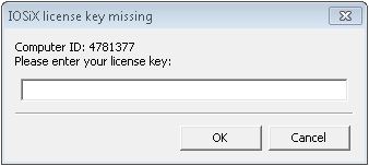
The IOSiX software will generate a computer ID for your specific computer. Send this ID to info@iosix.com so a license key can be generated. Note that this license key will only be valid for a particular computer, and will work across re-installs. Additional license keys are available for a discounted price. Site licenses are also available that are not tied to a specific computer ID.
2.Windows Toolbar
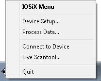
When the software is launched, it will appear as an icon on the windows toolbar.
To open the various screens, click on the icon and the menu will appear.
To open the various screens, click on the icon and the menu will appear.
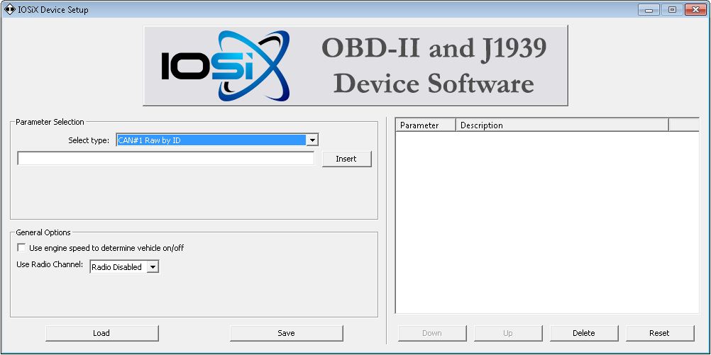
3. Device Setup
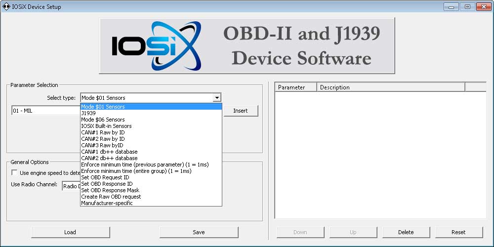
Drop-down selection menu
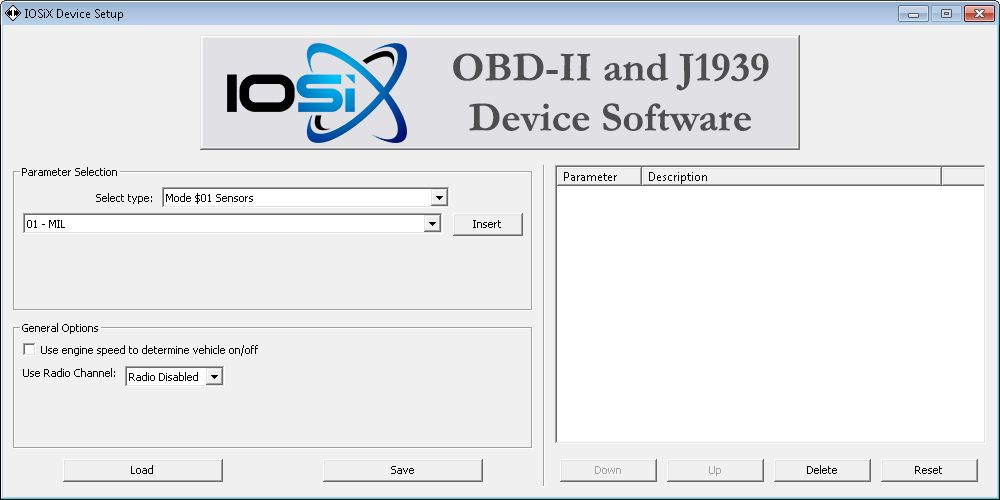
Blank configuration
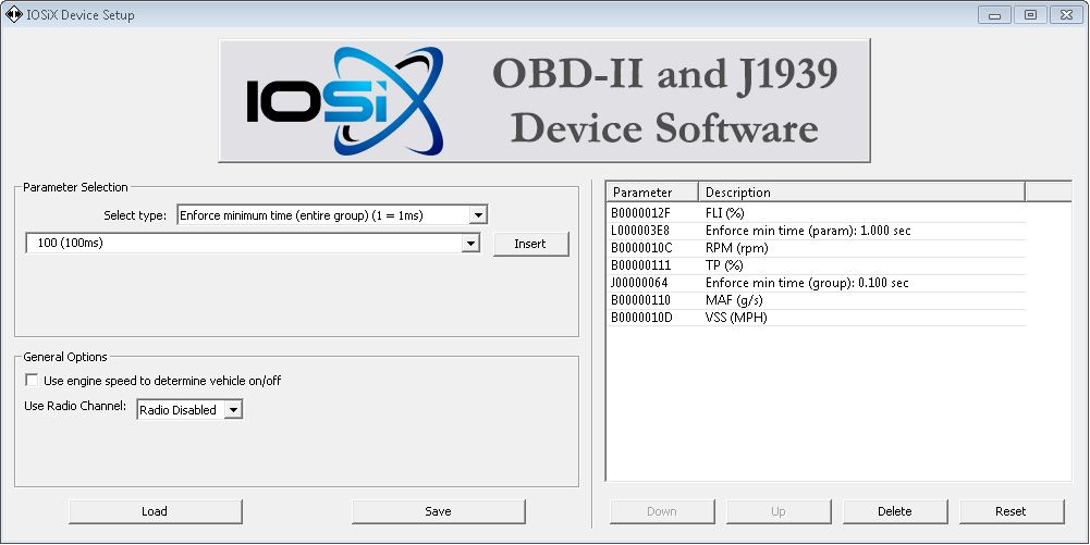
Example OBD-II configuration
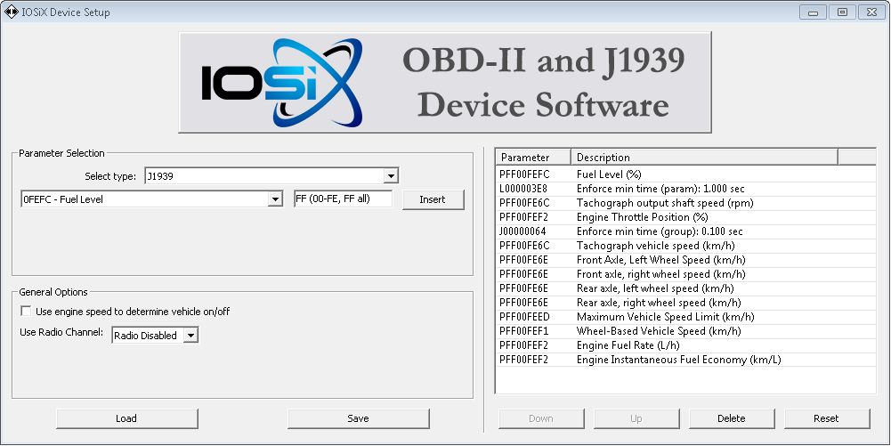
Example J1939 configuration
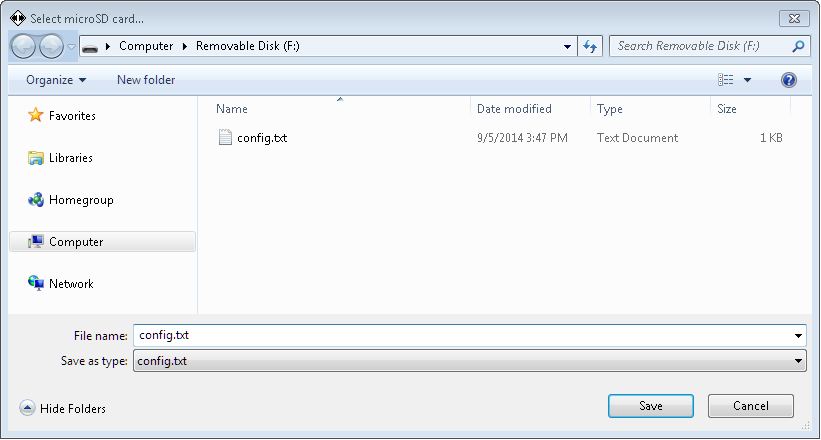
Generated config.txt file is to be saved to root directory of device storage
3.1 OBD-II
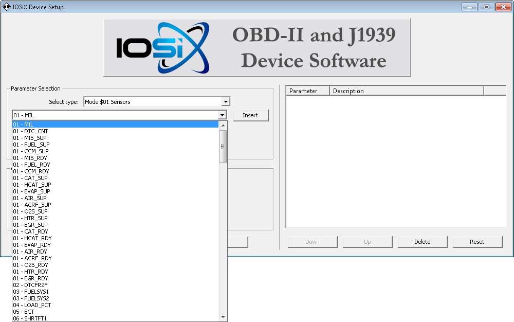
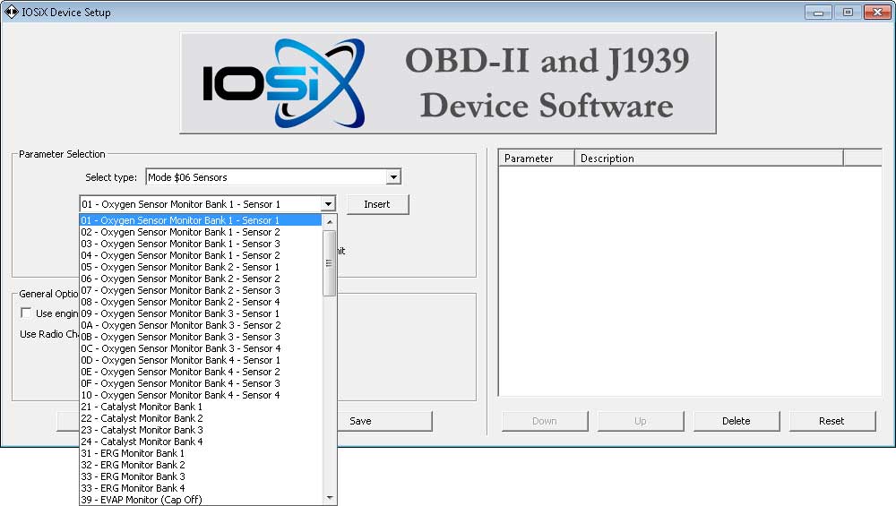
Use Mode $01 for generic sensor data, and Mode $06 for O2 sensor diagnostics. Typically, it is recommended to keep the data rate under 10Hz (aggregate of all parameters) for old pre-CAN vehicles; CAN vehicles can often support 50-100Hz without issue. Make sure to test your configuration and that there are no vehicle anomalies (especially with the dashboard and ABS/stability systems) if you are using higher rates in the field. The logger will dynamically adapt to the parameters that are available on the vehicle, so if you select something that isn’t supported it won’t slow down data acquisition by continuing to request non-supported parameters.
Mode $01 drop-down
Mode $06 drop-down
3.2 J1939
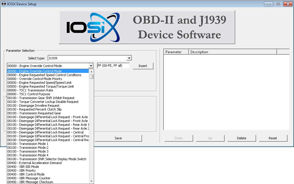
The full J1939 parameter list is available in the software, and you can specify the source address you’d like to use using the box to the right of the parameter (FF default allows it to accept from all source addresses).
3.3. Timing Control
The timing control options permit you to control the rate at which different parameters are recorded/requested. If no timing is specified for a parameter, the logger defaults to full speed. Timing units are in milliseconds, so 1000 would be used to acquire data at 1Hz.
OBD-II requests
For OBD-II parameters, the timing control specifies the minimum period to wait between requests. Note that if the vehicle cannot keep up with the requested timing the rates are slowed down so that all parameters can be aquired. This is done via round-robin scheduling.
CAN/J1939 data
For streaming data (that doesn’t need to be requested), the device will accept new data for that message once the desired interval time has elapsed.
Enforce minimum time (parameter)
The parameter immediately above the timing setting is forced to the interval timing specified.
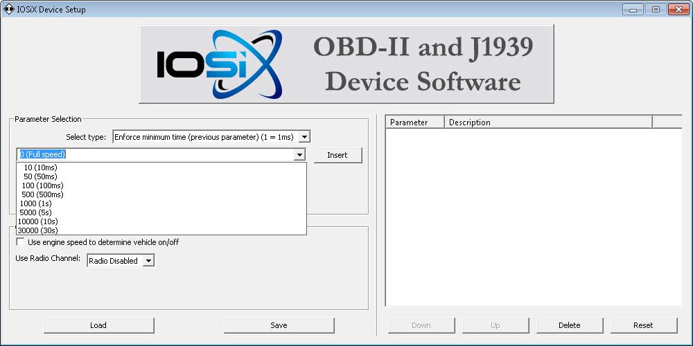
Enforce minimum time (entire group)
All parameters preceding the timing setting (that haven’t been assigned timing yet) are set to the interval timing specified.

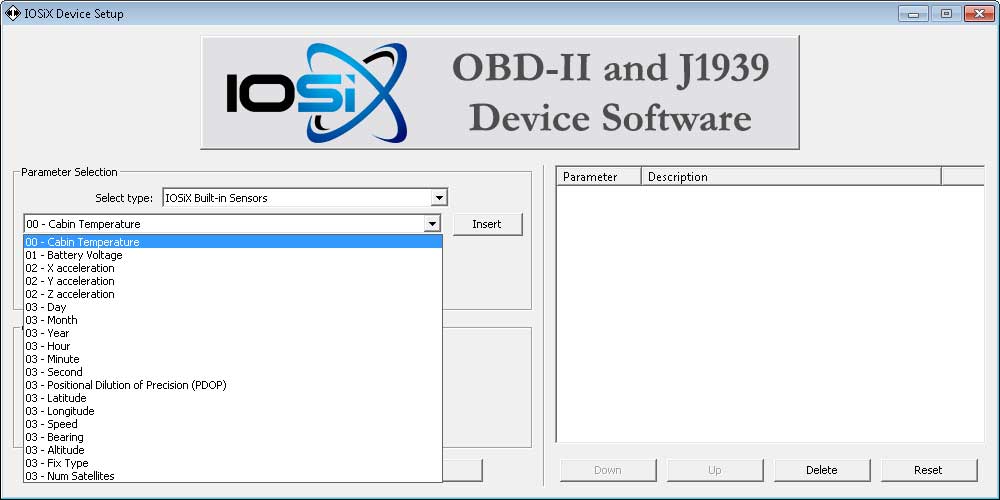
3.4.Built-in Sensors
This allows you to record data from the sensors built into the logger. This includes battery voltage, accelerometer data, temperature data, battery voltage, and GPS position. By default, if the unit is equipped with GPS and no GPS parameters are selected in the config.txt, a separate .GPS file is created with the GPS trace.
3.5.OBD-II advanced settings
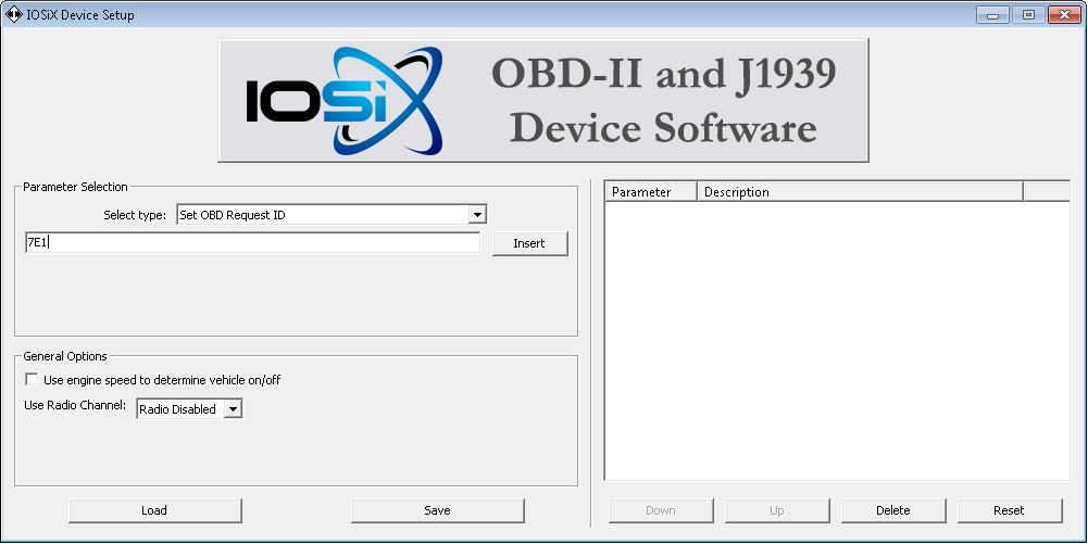
Set OBD Request ID
This option lets you define a custom transmit address for OBD-II requests on CAN. This address is also used for flow control for long responses, automatically. Standard 11-bit setting is 7DF for a functional request.
3.8.Raw CAN
The device supports acquiring raw CAN data at up to full line speed on multiple buses. This is primarily used by automotive and truck OEMs who possess the information to decode the CAN packets.
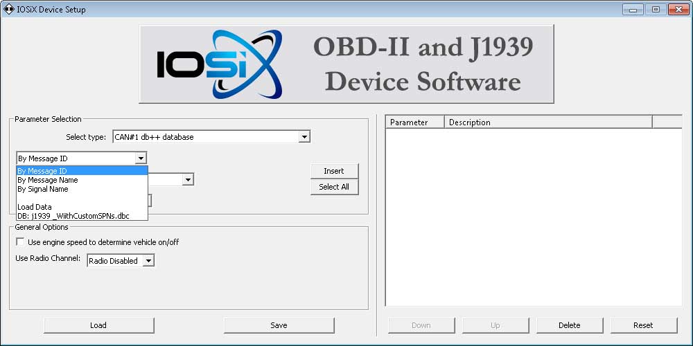
Using CANdb++ database
This mode allows the software to interoperate with the Vector CANtech .DBC standard for specifying CAN messages. You can import a file and choose signals directly.
Using CAN message address directly
This mode allows you to enter the CAN address of a message you’d like to acquire.
4.Post-Processing
The Post-Processing window is used to convert IOS and ACC binary files to human-readable format with engineering units. The output is a .CSV file suitable for use with Excel and a variety of off-the-shelf and custom solutions.
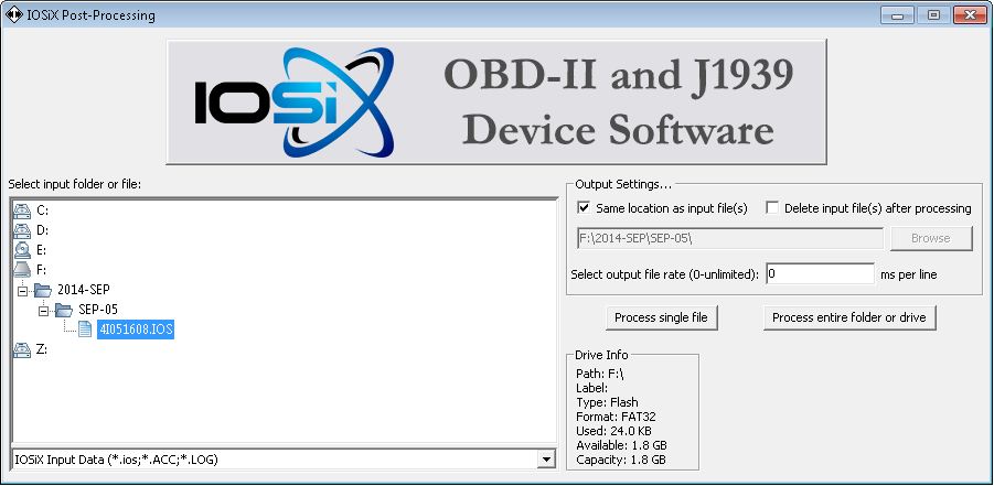
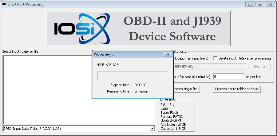
Processing will proceed with a status dialog
Processing data collected without a configuration
In this case, the software will ask you how to process the data. You can extract the raw CAN packets, treat the data as J1939, or apply a custom .dbc file.
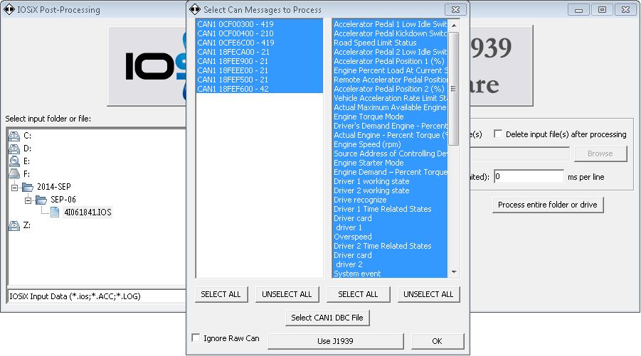
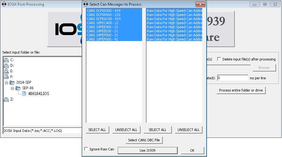
Raw CAN/dbc mode
5. Filesystem Structure
The root directory of the microSD card or eMMC flash filesystem contains two special, optional files:
- config.txt
- Tells the device what parameters to log and at what rates
- Contains instructions for the post-processor
- Format is open to enable development of custom software (contact IOSiX for details)
- prefs.txt
- Configures a variety of device settings, such as wakeup mode, WiFi and cellular settings, baud rates, etc.
Data folders are organized by year and month.
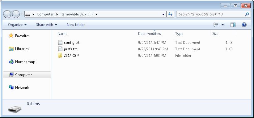
A folder is created within each month folder for each day data is recorded.
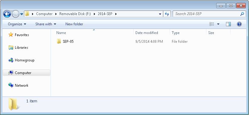
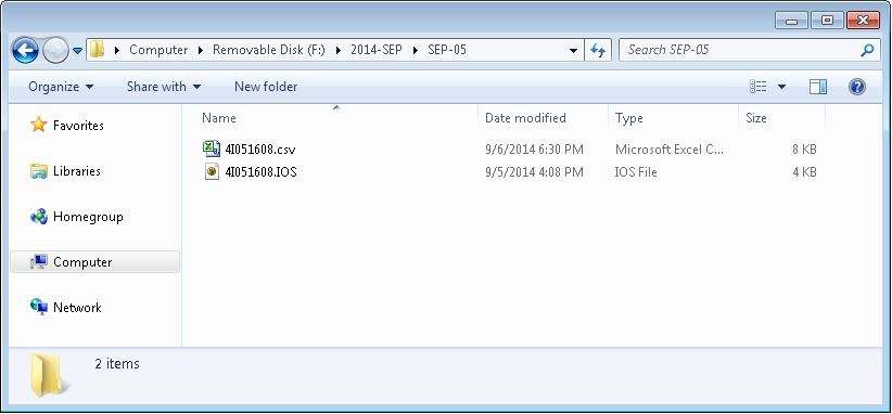
The data files are stored within the day folders, and are named using the following format:
<last digit of year><letter for month, Jan = A><two digit day of month><two digit hour><two digit minute>
So, 4I051608 would be 4:08pm on September 5, 2014.
File types:
- .IOS files contain IOSiX binary data (format available upon request)
- .CSV files contain comma-separated data suitable for opening in a tool such as Excel
- .GPS files contain GPS data in CSV format
- .ACC files contain high-speed binary accelerometer data (format available upon request)
